Author: Andrew Mourcos
Published: 03 Feb 2023
Description: How we dealt with buck converters in our circuit design
Dealing with Buck Converters (Jan 30 - Feb 3)
Recently, a few people have asked me for circuit design tips when using a buck converter, so I decided to make that the topic of this week’s blog as I’m currently working on power conversion on our electronics module. If you’re unfamiliar, a buck converter is a type of DC-DC converter that’s commonly used to step down voltage to meet the requirements for powering devices on a PCB. There are also other types of voltage step down devices (like LDOs), but bucks benefit from very high efficiency.
I’ll start by introducing the basic operating principle, then I’ll walkthrough an example of how I sized the inductor for the buck on our project.
Basic Structure of a Buck
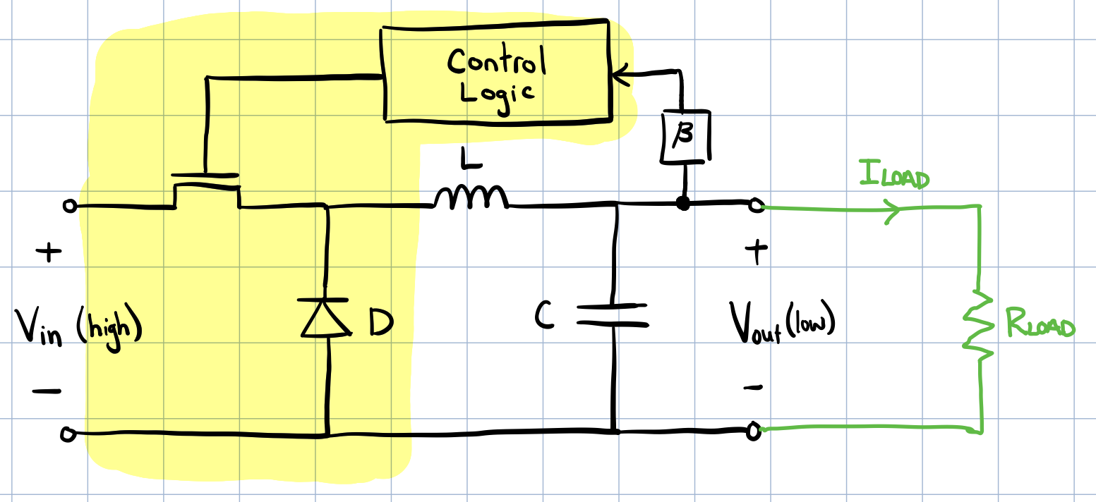
 Buck converter circuit
When designing a buck converter circuit, there are several key components that are required. These include:
-
Switching element (MOSFET): The switching element is responsible for turning the input voltage on and off at a high frequency. MOSFETs are commonly used due to their high efficiency and fast switching times.
-
Inductor: The inductor is used to store energy during the on-time of the MOSFET and release that energy to the output capacitor during the off-time of the MOSFET. The value of the inductor is determined by the desired output current and the switching frequency.
-
Output capacitor: The output capacitor is used to filter the output voltage, smoothing out any ripple caused by the switching frequency. The value of the output capacitor is determined by the desired output voltage and the load current.
-
Diode: The diode is used to allow current to flow from the inductor to the output capacitor during the off-time of the MOSFET.
-
Control circuitry: The control circuitry is responsible for regulating the output voltage by adjusting the duty cycle of the switching element. This can be done using a feedback loop, where the output voltage is compared to a reference voltage and the duty cycle is adjusted accordingly.
Annotated in the previous figure, the switching element, control circuitry and diode are often lumped together in a single IC. That leaves the circuit designer to focus on choosing items 2 and 3 above.
Sizing an Inductor
Here, I’ll outline the steps I took in selecting an inductor for a buck converter used on our ring. The first thing to do is collect a few key pieces of information:
- \(V_{out}\): Output voltage - design requirement
- \(V_{in}\): Input voltage - design requirement
- \(\eta\): Efficiency (estimate) - plots in the datasheet
- \(f_{sw}\): Average switching frequency - electrical characteristic in the datasheet
- \(I_{LIM,MIN}\): High-side peak current - electrical characteristic in the datasheet
- \(I_{OUT,MAX}\): Max current draw of load (estimate) - take measurements
After gathering that information, we approximated the switching duty-cycle as follows:
\[\delta = \frac{V_{out}}{V_{in}\cdot\eta}\]Next, it was necessary to estimate the inductor ripple current. Admittedly, we have a bit of a dillema here - we need to know the inductance to figure out the ripple. Since we just need an estimate, we can look at the datasheet’s recommended range of inductor values and use the median in our calculation as a starting point (call this \(I_{AVG}\)):
\[\Delta I_L = \frac{ (V_{in}-V_{out})\cdot\delta }{ f_{sw}\cdot L_{AVG} }\]Finally, we can get a lower bound on the inductor size:
\[L_{min} = \frac{V_{out} \cdot (V_{in} - V_{out})}{V_{in}\cdot f_{sw} \cdot \Delta I_L}\]That’s it. At this stage, you should also do a quick sanity check that the buck can handle the load’s current draw:
\[I_{IC,MAX} = I_{LIM,MIN} - \frac{1}{2}\Delta I_L\]Closing Remarks
In summary, designing a buck converter circuit requires careful consideration of several key components. These include the switching element, inductor, output capacitor, diode, and control circuitry. By properly sizing the inductor, you can help the circuit meet the required specifications and operate efficiently.
While this post only provides a brief overview of inductor sizing, I hope it provides a helpful starting point for those looking to delve deeper into this topic. As always, it’s important to consult datasheets and other resources to ensure that your design meets the necessary requirements.